Our testing included a 1/4 wave ground plane, home-made from a set of four 20" copper wires soldered to the corners of a panel mount
SO239 bulkhead connector, and a tuned copper center conductor for 2m, 220 or 440, soldered to the center pin of the SO239 connector.
The 1/4 wave ground plane antenna served as a reference for the other two antennas.
Ed Fong TBJ-1The Ed Fong TBJ-1 antenna is a multipurpose (including ham radio) 7 foot tall antenna made of PVC tubing with two end-caps, both removable. The bottom end-cap is drilled for either a SO239 socket or N socket. The antenna has no mounting hardware but it can be suspended from the top or mounted with user supplied brackets. Housing and mounting modifications can be made to the antenna using store-bought PVC accessories and PVC glue. The antenna is sold direct from the manufacturer at [email protected] for $60 plus $13 shipping. Ed Fong has a website at Ed's Antennas. Down near the bottom of that page you can find a PDF download titled fong-qst-2017-march.pdf which is the QST story about the TBJ-1 antenna.Ed Fong designed the antenna to have no ground radials and to have a low price. Furthermore it can be taken out of service and tossed in the back of a truck with very little chance of damaging the antenna. The antenna is shipped in its single piece housing. The antenna is ideal for dragging through a pipe or through foliage because it has no horizontal projections or anything to snag. The antenna is made from easily obtained PVC tubing so even if run over by a truck, it could be salvaged and repaired. |
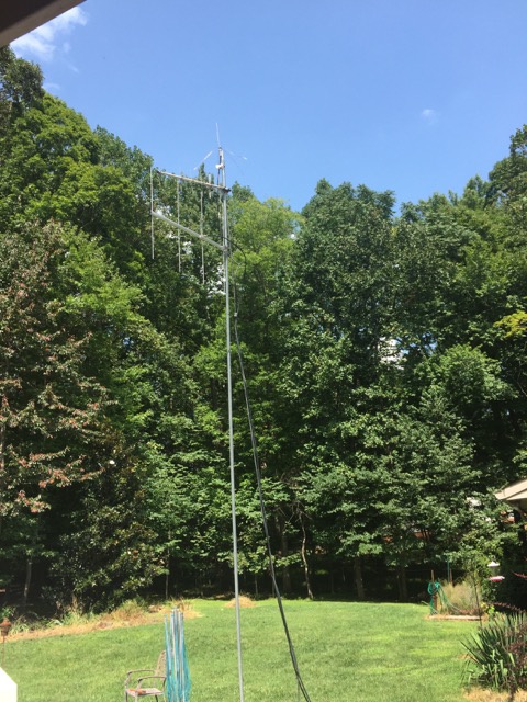
on top of our 20' high moveable mast. The 2m and 440 yagis, used for packet radio, are non functional in this test. |
The coax connector is out in the environment so waterproofing must be added. Support mechanism must be added by the user as no U-clamps or brackets of any kind are supplied.
The TBJ-1 antenna is a recent addition to the lineup as of late 2016 or early 2017.
Comet CX-333
The Comet CX-333 is a made for ham-radio base-station service 10 foot tall ground plane, mast mounted (support for 1" to 2.5" mast) with four rigid 20" ground radials at the bottom. The coax connector, after installation, is out of the weather in the 8" long pipe which serves as the support for the antenna. The antenna sits on and is locked into the top of that pipe with a single hex-head machine bolt. The 8" long pipe is secured to the mast with a pair of included cast brackets incorporating a built-in saddle shape and two U-clamps. Assembly is trivial and the unit appears very professional and mechanically sound. It looks like it could survive or 15 years on a tall tower. The Comet antenna company US representatives accept emails from their vendors and are very responsive with replacement parts (in my experience with a different antenna, shipped directly to the customer without any commitment for return or payment!).
The antenna, after disassembly (in the case of removal) is in six pieces, some with lose screws.
If tossed in the back of a truck without disassembly, damage is inevitable.
Comet antennas do survive well but the outer shell begins to chalk after a year or two outdoors.
This model of antenna has been on the market since 2003 or before.
Instructions are available here: CX-333-manual.pdf
The Comet antenna is shipped for about $170 from several ham vendors including Ham Radio Outlet.
Our Results
| band | Ed Fong TBJ-1 | Comet CX-333 |
| 2m band | 3.1dB better than the ground plane | 3.7dB better than the ground plane |
| 220 band | 4.7dB worse than the ground plane | 0.7dB better than the ground plane. | 440 band | 8dB worse than the ground plane | 1.7dB better than the ground plane |
Experimental Method
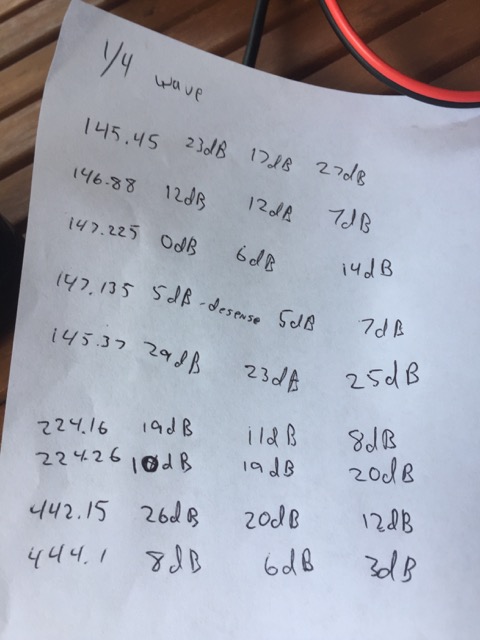
Our plan was to find several repeaters on each of the three covered bands and work each repeater from several locations by moving the masts. We ended up with five 2m band repeaters, two 220 band repeaters, and two 440 band repeaters. The number of 220 and 440 repeaters was limited by the range from our 1/4 wave antenna and our location, seven miles northwest of Durham NC. We mounted the antennas sequentially on a 20' mast on the pool patio behind a single-story house which is somewhat above average terrain though surrounded by 70' to 90' high trees. We tested against each of the repeaters, then moved the mast and tested again. All moves were 5' or more. A total of 81 separate radio tests were performed. The 1/4 wave antenna tests were done between 2pm and 3pm. After doing the 1/4 wave tests and gathering 3 test numbers for each repeater, we removed the 1/4 wave and mounted the CX-333. The Comet CX-333 tests were done between 3:30pm and 4pm. After the Comet CX-333 we mounted the Ed Fong TBJ-1 antenna and ran its numbers. Those were between 4:30pm and 5:20pm. I don't know if the time of day had anything to do with performance. I suspect not. The numbers were gathered by running a Kenwood TH-F6A HT 3-band HT through a 10dB attenuator, and then into a 1dB step attenuator. The attenuation numbers listed are in addition to 10dB attenuation on the output of the Kenwood TH-F6A HT in high power. While listening on another triband radio on a separate 3-band antenna, we keyed up each of the repeaters and tested the maximum attentuation we could put in line to BRING-UP the repeater. We weren't interested in how strong we were through the repeater, only that the repeater would come up. The method was to assert high attenuation, start a transmission, and then reduce the attenuation until the repeater keyed. After the repeater was up I did verification by toggling the attenuation in and out to see if this was consistent. On some repeaters the key-up level was higher than the level required to keep the repeater keyed (hysteresis). On others the key-up level was lower than the level required to keep the repeater keyed (de-sence). The antennas used included an Ed Fong triband antenna TBJ-1 purchased October 13, 2015. The other antenna was a Comet CX333 triband vertical from HRO $160 purchased in August 2017. The 1/4 wave antenna was made from ROMEX house wire and a SO239 4-screw bulkhead connector.
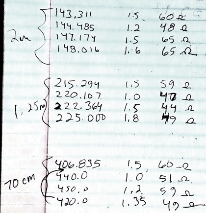
The raw data is attached below and also a spreadsheet where we made calculations.
Also there are photographs and videos of the event which we’ll put together later.
DiscussionI would like to have more data to get a more accurate result. I didn’t want to run the HT into the step attenuator without first dropping it’s signal. I didn’t want to break the step attenuator. With only 700mW (best guess) and with the 1/4 wave ground plane as the start antenna I rejected any repeaters which were not workable with the ground plan antennas. Thus we could only bring up two repeaters on 220 and two repeaters on 440. As you can see from the test data, the gain delta between the antennas is not much different than the delta in path performance shown by moving the antenna. We may want to have more antenna positions per repeater. We needed to be much quicker about this because I don’t think we could double the number of sites without incurring potential time-of-day effects on our results. See photos attached for test setup, raw data recorded on pen and paper, and a photo showing the mounting position and the 1/4 wave antenna in its 2m configuration. The two yagis were not used in testing and were below the plane of the ground plane. No measurement of stray RF on the coax was made. This is probably something which should be performed. | 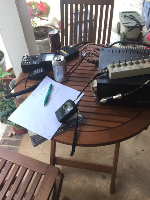 The antenna analyzer, Kenwood HT, 10dB attenuator, and KAY step attenuator are visible in this photo, along with notes-in-progress. |
Phone call with Ed
I got on the phone with Ed. He's a really nice guy and has lots of experience and good equipment. He said his goals did not include competitive performance with the big antenna companies. He was going for durable and cheap. I showed him our numbers from this test. He complemented us on our nearly unbelievably accurate results. He said that the TBJ-1 should perform 10dB worse than the CX-333 on 440 and 6dB worse on 220 because the CX-333 has stacked 5/8 wave antennas, five of them on 440. He complemented Comet as a manufacturer and said they don't lie about their specs. He said some of the knock-off companies are complete liars. He mentioned names and so did I but I'm not looking for lawyers so I'll leave it at that. We did not talk about Diamond. I should have asked him about them. Ed said he recommends Arrow Antennas. He really likes Arrow's solid element yagis. Ed further said that the reason 1/4 wave ground planes sometimes work better, especially in our tests, is that by running the coax directly down below the ground plane that this flattens the radiation pattern, making the antenna perform very well indeed.Conclusion
- Quarter wave ground planes work very well, especially for their cost, but require separate coax runs, separate mounting positions, and a multiplexer to share coax.
- If you need a tri-band 144/220/440 antenna for long-term mounting at a base station, and are spending more than $200 on the radio and coax hooked to it, go with the CX-333.
- If you are going with a transient, emergency, backpacking, or frequently packed and unpacked set of gear, the TBJ-1 will likely be the better survivor.
- If you are going to hook a Chinese tri-band mobile radio to the antenna and cost is more of an object than performance, or ease of installation, then go with the TBJ-1.
- If your only use is 2m, there is nothing in the either of these antennas to recommend it so get a monoband J-pole, Hustler G6, or 1/4 wave ground plane.
- If going with attic use, make separate ground planes for each band. A wire ground plane using an SO239 socket costs about $3. Then work on some home-made wire yagi antennas or aluminum foil corner reflectors.
- If cost is an object and you need a roof-mount or tower mount antenna, use either a 1/4 wave ground plane from Arrow Antennas, or a Comet GP-1 antenna. Add a 220 yagi later?
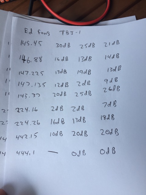
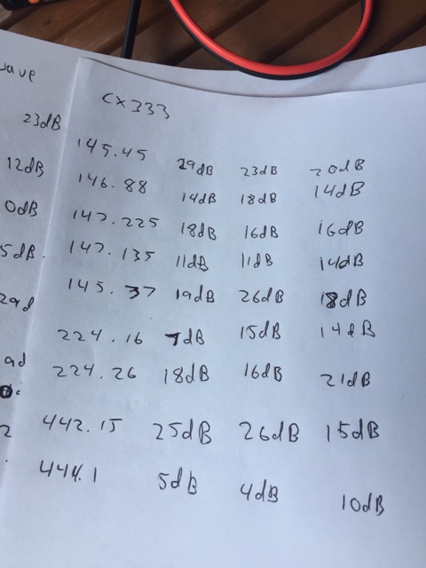
Alternative method
I came up with an alternative method of testing that would take less time and would allow a much greater number of test points, but it is not something readily reproducible without a ton of work.The alternative method of testing would be to drive down a known non-congested road while transmitting on a mobile radio, and record the S meter reading, using the test antenna, at a fixed location. The driver would indicate to the receiver that the test was starting at a known milemarker at which point the car would already be at the required speed, and in cruise control and the radio is transmitting. The driver would again indicate at the end of the test when passing the last milemarker.
Even if the actual speed were slightly different, so long as the speed was consistant the results would be compressible. This could easily be verified with multiple drives down the road with the same antenna.
Again attenuators are in between the receiver and test antenna and they would be adjusted only if the test run causes the S-meter to go out of range high or low. Any attenuator adjustment would necessitate a re-start of the drive and the data collection. The attenuator adjustment would be applied to the result. The S-meter would have to be interpreted automatically by a computer and automatically averaged.
I was thinking of using an Icom R7100 as the receiver, with it's analog S meter read by an Arduino board's AtoD input, or maybe a HobbyPCB RS-UV3 as the receiver. The RS-UV3 is a computer controlled transceiver sold for about $100. If the test runs were only a couple of miles per, and with two hams, a receiver operator and a driver, it is possible that we could test one band on one antenna in 10 minutes. I think the professionals use an RF anechoic chamber and a calibrated test antenna. We don’t have one of these.