model number SD110-SF2PASNM(F0455)
This is the label for the 45Mhz unit we tested. Click to enlarge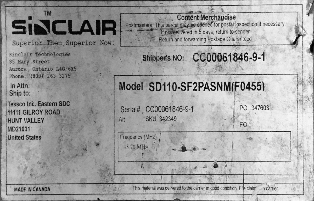 Sinclair page on this antenna. Note that the coverage listed is the range in which the antennas may be ordered.
The actual article after delivery is good for a few percent of frequency variation, I think.
Sinclair page on this antenna. Note that the coverage listed is the range in which the antennas may be ordered.
The actual article after delivery is good for a few percent of frequency variation, I think.
Here is Sinclair offering a dual-stack version. Two dipoles vertically colinear Here is Sinclair offering a quad-stack version. Four dipoles vertically colinear
Interesting links about folded dipoles for ham radio
Scribd: Building phasing harnessModifying the DB products DB-212 antenna from 43 to 6m ham band
Burt's page on the Sinclair 2m folded dipoles (including 6m)
Feb 11, 2017: Tad K4TD, Bob K4WCV, Tadd KA2DEW, and Ed (Bob's brother-in-law) set up a 45.5Mhz folded dipole and did some measurements using NC4FG's MFJ analyzer.
Photo with Bob, Tad and Tadd

We did measurements with the antenna horizontal, attached to its side-arms, held up over our heads. Then we mounted a 12' piece of masting to the sidearms about 3' away from the antenna and tested to see if there was any difference.
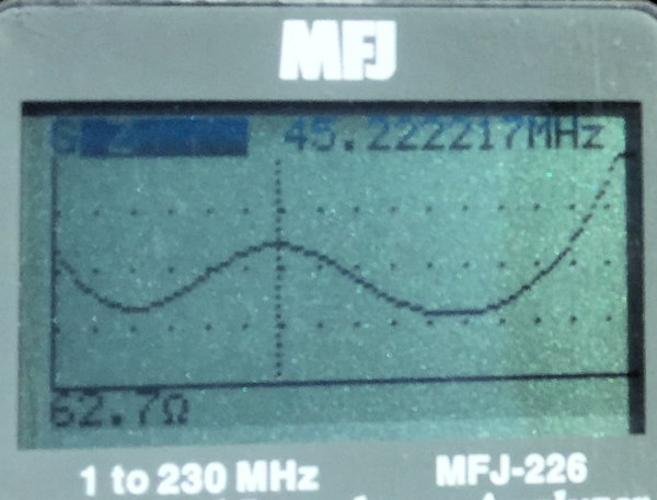
The instrument was set to scan from 40 to 54Mhz. The top of the instrument was 3:1 during SWR measurements and 100ohms during impedance measurement.
Tad K3TD holding the antenna up just before Bob K4WCV grabbed it from the bottom so we could make a "free space" test
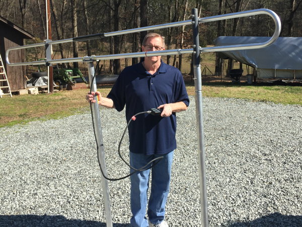
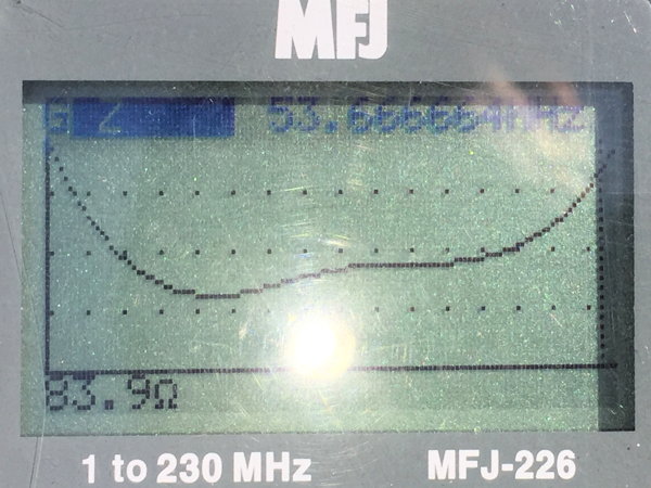
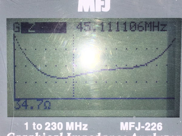
Tad and Bob held the antenna straight up over their heads while I made and photographed these measurements:
IMG_1154 SWR measured @53.66Mhz is 1.96:1.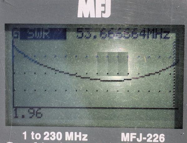 |
| IMG_1155 84ohm [email protected] | IMG_1156 34.6 ohms at 45.11Mhz |
 |  |
IMG_1157cr (click to enlarge)

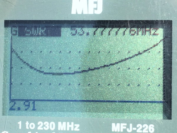
Then we mounted the mast underneath the antenna at a roughly 3' spacing. At the time I didn't have the instruction paper specifying the correct distance. The distance is frequency specific anyway. What I wanted to know is if the readings would be affected by the mast. During the test, Bob and Tad stayed below the level of the horizontal mast piece.
IMG_1158 SWR of 3:1 at 53.77Mhz
| IMG_1159 | IMG_1161 |
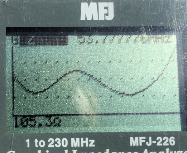 |  |
The answer is, putting in the masting moved the dip in the SWR down frequency, making 53.63 have a worse SWR. It also impacted the impedance a bit.
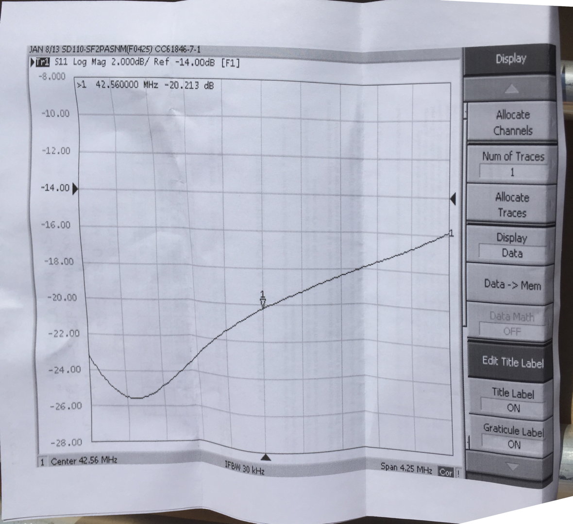
This next document is from the 42.56Mhz version of the antenna. This shows us the requested spacing between the tower and the centerline of the antenna. We were pretty close. Click to enlarge
IMG_1164cr
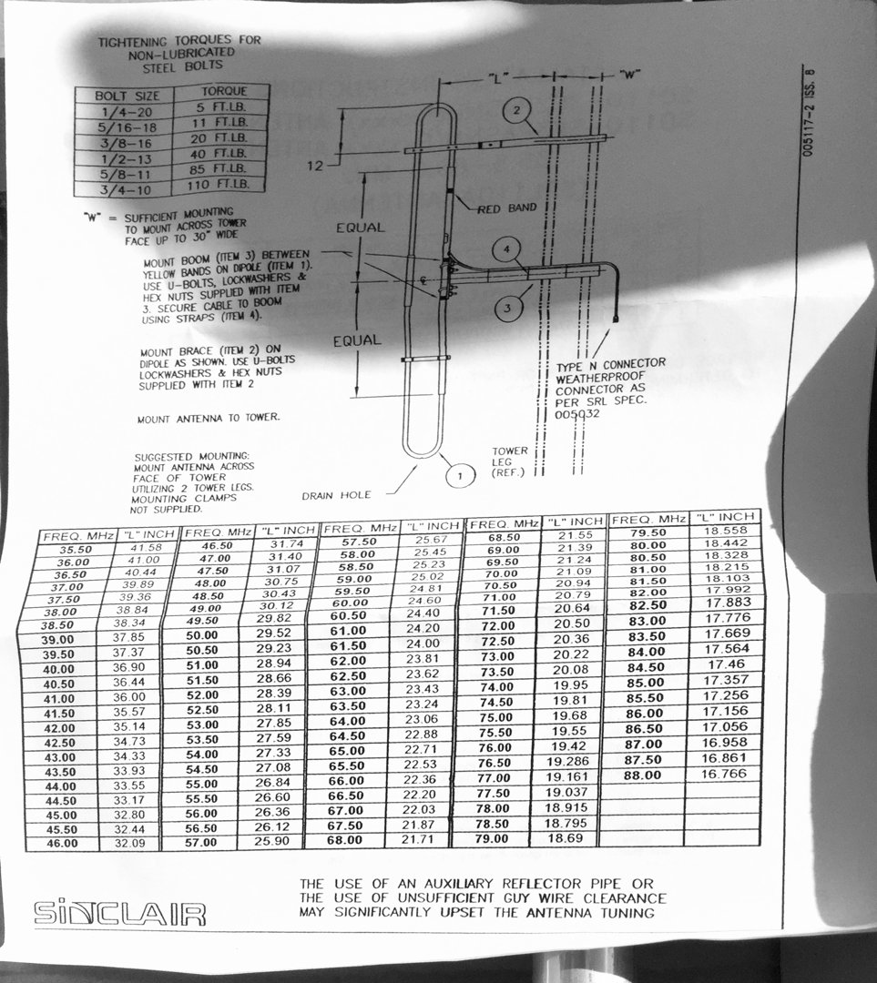
I don't know what this page shows. It was attached to the chart in the previous page.
IMG_1165cr